---
id: 1127
card_url: "https://mdrss.com/platforms/infrastructure-and-networking/1127"
permalink_url: "https://mdrss.com/m/1127"
thread_url: "https://mdrss.com/s/platforms"
markdown_url: "https://mdrss.com/platforms/infrastructure-and-networking/1127/1127.md"
title: "Guide to NetPractice"
annotation: "Korean French Spanish --- TCP stands for Transmission Control Protocol. It is a communications standard that enables application programs and devices to exchange messages over a network."
state: published
thread: platforms
domain: platforms
category: infrastructure-and-networking
type: guide
tags: ["netpractice", "network", "tcp", "infra"]
ontology_terms: []
relation_terms: []
license: "MIT"
version: 1
snapshot_at: "2026-08-04T12:18:57.105Z"
source_url: "https://github.com/lpaube/NetPractice"
source_kind: "mdrss-final-catalog"
platform_scam_risk: null
platform_evidence_score: 0
evidence_urls:
- "https://github.com/lpaube/NetPractice"
---
# Guide to NetPractice

## Other Languages
[Korean](https://github.com/lpaube/NetPractice/blob/HEAD/README.ko.md)
[French](https://github.com/lpaube/NetPractice/blob/HEAD/README.fr.md)
[Spanish](https://github.com/lpaube/NetPractice/blob/HEAD/README.es.md)
## Table of Contents
- [Important concepts](#important-concepts)
- [TCP](#tcp-transport-layer)
- [IP address](#ip-address-network-layer)
- [Subnet mask](#subnet-mask)
- [Switch](#switch)
- [Router](#router)
- [Levels](#levels)
---
## Important Concepts
### TCP: Transport Layer

TCP stands for **Transmission Control Protocol**. It is a communications standard that enables application programs and devices to exchange messages over a network. It is used to send packets across the internet.
TCP guarantees the integrity of the data being communicated over a network. Before it transmits data, TCP establishes a connection between a source and its destination, which remains active until communication begins. It then breaks large amounts of data into smaller packets, while ensuring end-to-end delivery without loss of any data.
---
### IP Address: Network Layer
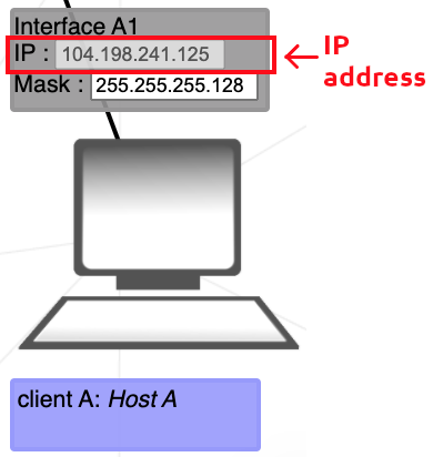
IP is part of an internet protocol suite, which also includes the transmission control protocol. Together, these two are known as TCP/IP. The internet protocol suite governs rules for packetizing, addressing, transmitting, routing, and receiving data over networks.
IP addressing is a logical means of assigning addresses to devices on a network. Each device connected to the internet requires a unique IP address.
An IP address has two parts; one part identifies the host such as a computer or other device, and the other part identifies the network it belongs to. TCP/IP uses a [subnet mask](#subnet-mask) to separate them.
#### IPv4 vs. IPv6
IP addresses come in 2 versions--IPv4 and IPv6:

Internet Protocol version 4 (IPv4) defines an IP address as a 32-bit number. However, because of the growth of the Internet and the depletion of available IPv4 addresses, a new version of IP (IPv6), using 128 bits for the IP address, was standardized in 1998. However, only IPv4 addresses are used in NetPractice.
#### Public Address vs. Private Address
A public IP address is an IP address that can be accessed directly over the internet and is assigned to your network router by your internet service provider (ISP). A public (or external) IP address helps you connect to the internet from inside your network, to outside your network.
A private IP address is an address your network router assigns to your device. Each device within the same network is assigned a unique private IP address (sometimes called a private network address) — this is how devices on the same internal network talk to each other.
When a network is connected to the internet, it cannot use an IP address from the reserved private IP addresses. The following ranges are reserved for private IP addresses:
```
192.168.0.0 – 192.168.255.255 (65,536 IP addresses)
172.16.0.0 – 172.31.255.255 (1,048,576 IP addresses)
10.0.0.0 – 10.255.255.255 (16,777,216 IP addresses)
```
---
### Subnet Mask
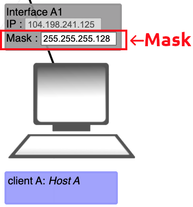
A subnet mask is a 32 bits (4 bytes) address used to distinguish between a network address and a host address in the IP address. It defines the range of IP addresses that can be used within a network or a subnet.
#### Finding the network address
The _Interface A1_ above has the following properties:
```
IP address | 104.198.241.125
Mask | 255.255.255.128
```
To determine which portion of the IP address is the network address, we need to apply the mask to the IP address. Let's first convert the mask to its binary form:
```
Mask | 11111111.11111111.11111111.10000000
```
The bits of a mask that are 1 represent the network address, while the remaining bits of a mask that are 0 represent the host address. Let's now convert the IP address to its binary form:
```
IP address | 01101000.11000110.11110001.01111101
Mask | 11111111.11111111.11111111.10000000
```
We can now apply the mask to the IP address through a [bitwise AND](https://en.wikipedia.org/wiki/Bitwise_operation#AND) to find the network address of the IP:
```
Network address | 01101000.11000110.11110001.00000000
```
Which translates to a network address of `104.198.241.0`.
#### Finding the range of host addresses
To determine what host addresses we can use on our network, we have to use the bits of our IP address dedicated to the host address. Let's use our previous IP address and mask:
```
IP address | 01101000.11000110.11110001.01111101
Mask | 11111111.11111111.11111111.10000000
```
The possible range of our host addresses is expressed through the last 7 bits of the mask which are all 0. Therefore, the range of host addresses is:
```
BINARY | 0000000 - 1111111
DECIMAL | 0 - 127
```
To get the range of possible IP addresses for our network, we add the range of host addresses to the network address. Our range of possible IP addresses becomes `104.198.241.0 - 104.198.241.127`.
HOWEVER, the extremities of the range are reserved for specific uses and cannot be given to an interface:
```
104.198.241.0 | Reserved to represent the network address.
104.198.241.127 | Reserved as the broadcast address; used to send packets to all hosts of a network.
```
Therefore, our real IP range becomes `104.198.241.1 - 104.198.241.126`, which could have been found using an [IP calculator](https://www.calculator.net/ip-subnet-calculator.html).
#### CIDR Notation (/24)
The mask can also be represented with the Classless Inter-Domain Routing (CIDR). This form represents the mask as a slash "/", followed by the number of bits that serve as the network address.
Therefore, the mask in the example above of `255.255.255.128`, is equivalent to a mask of `/25` using the CIDR notation, since 25 bits out of 32 bits represent the network address.
---
### Switch
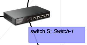
A switch connects multiple devices together in a single network. Unlike a router, the switch does not have any interfaces since it only distributes packets to its local network, and cannot talk directly to a network outside of its own.
---
### Router
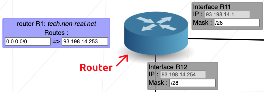
Just as the switch connects multiple devices on a single network, the router connects multiple networks together. The router has an interface for each network it connects to.
Since the router separates different networks, the range of possible IP addresses on one of its interfaces must not overlap with the range of its other interfaces. An overlap in the IP address range would imply that the interfaces are on the same network.
#### Routing Table
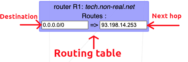
A routing table is a data table stored in a router or a network host that lists the routes to particular network destinations. In NetPractice, the routing table consists of 2 elements:
- **Destination**: The destination specifies a network address on which a host is the end target of the packets. The route of `default` or `0.0.0.0/0`, is the route that takes effect when no other route is available for an IP destination address. The default route will use the next-hop address to send the packets on their way without giving a specific destination. The default route will match any network.
- **Next hop**: The next hop refers to the next closest router a packet can go through. It is the IP address of the next router on the packet's way. Every single router maintains its routing table with a next hop address.
## Levels
Level 1
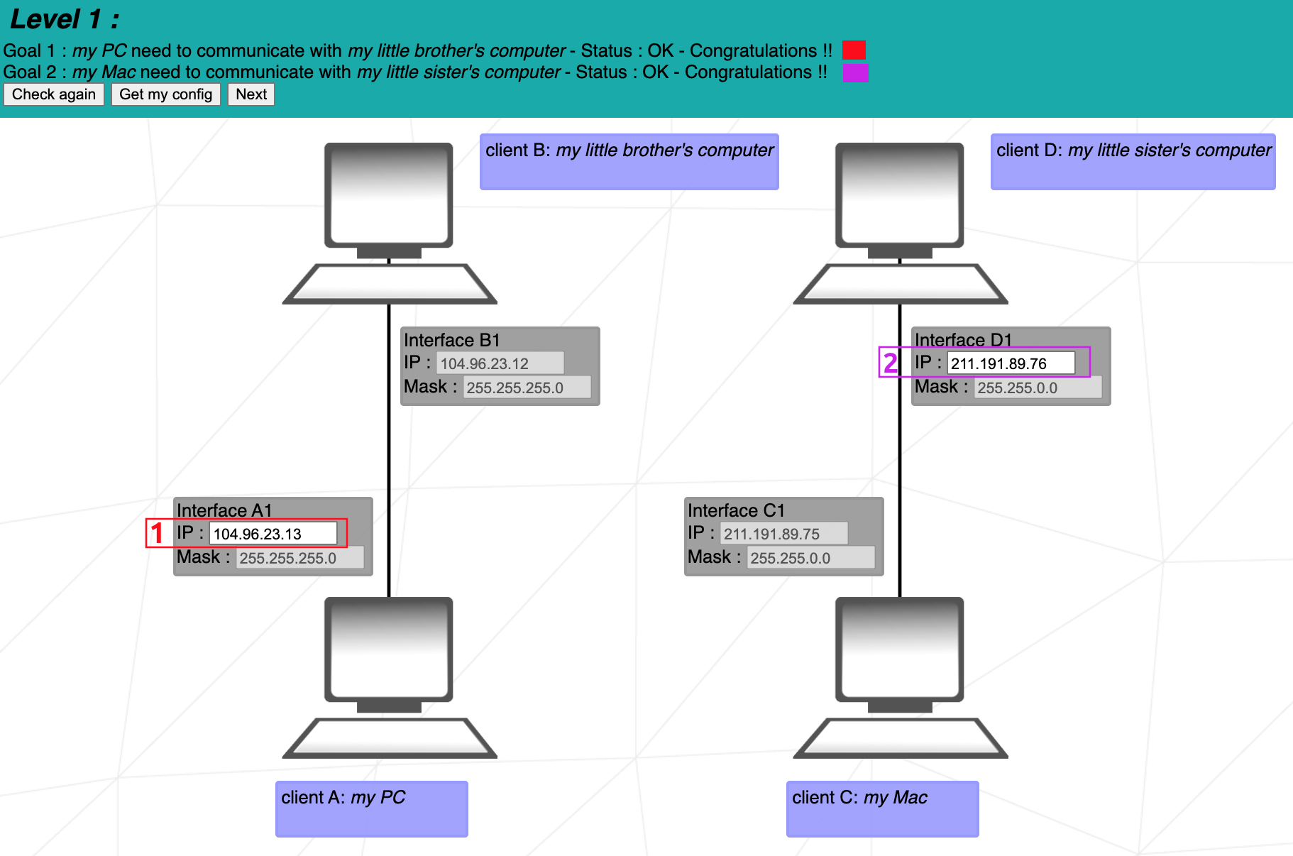
**1.** Since _Client A_ and _Client B_ are on the same network, their IP address must represent the same network in accordance with the subnet mask.
The subnet mask is _255.255.255.0_, which means that the first 3 bytes of the IP address represent the network, and the 4th byte represents the host. Since we are on the same network, only the host can change.
The solution will be anything in the range of **104.96.23.0 - 104.96.23.255** excluding the following 3:
- **104.96.23.0:** The first number in the range of hosts (0 in this case) represents the network and cannot be used by a host.
- **104.96.23.255:** The last number in the range of hosts (255 in this case) represents the broadcast address.
- **104.96.23.12:** This address is already used by the host _Client B_.
**2.** The same reasoning as _1._, however the subnet mask is _255.255.0.0_ in this case. The first 2 bytes of the IP address will represent the network; and the last 2 bytes, the host address.
The solution will be anything in the range of **211.191.0.0 - 211.191.255.255**, excluding:
- **211.191.0.0:** Represents the network address.
- **211.191.255.255:** Represents the broadcast address.
- **211.191.89.75:** Already taken by host _Client C_.
---
Level 2
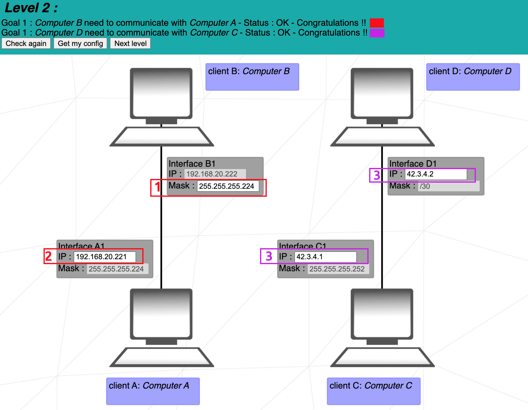
**1.** Since _Client B_ is on the same private network as _Client A_, they should have the exact same subnet mask.
The solution can only be **255.255.255.224**.
**2.** To understand the subnet mask of _255.255.255.224_, let's look at it in binary form, along with the IP _192.168.20.222_ of _Client B_:
```
MASK: 11111111.11111111.11111111.11100000
IP: 11000000.10101000.00010100.11011101
```
As we can see, the first 27 bits represent the IP address, while only the last 5 bits represent the host address.
All these 27 bits representing the network must stay the same in the IP addresses of hosts on the same network. To get the answer, we can only change the last 5 bits.
The answer is in the range of:
```
BIN: 11000000.10101000.00010100.11000000 - 11000000.10101000.00010100.11011111
or
DEC: 192.168.20.192 - 192.168.20.223
```
Excluding:
- **11000000.10101000.00010100.11000000:** Represents the network address (notice all 0 in the last 5 bits).
- **11000000.10101000.00010100.11011111:** Represents the broadcast address (notice all 1 in the last 5 bits).
- **11000000.10101000.00010100.11011110:** _Client B_ already has that address.
**3.** Here we are introduced the slash "/" notation for the subnet mask on _Interface D1_. A subnet mask of _/30_ means that the first 30 bits of the IP address represent the network address, and the remaining 2 bits represent the host address:
```
Mask /30: 11111111.11111111.11111111.11111100
```
We can see that this binary number corresponds to the decimal _255.255.255.252_, therefore it is identical to the mask found on _Interface C1_.
The answers can then be any address, as long as they meet the following conditions:
- The network address (first 30 bits) must be identical for _Client D_ and _Client C_.
- The host bits (last 2 bits) cannot be all 1, nor all 0.
- _Client D_ and _Client C_ do not have identical IP addresses.
---
Level 3
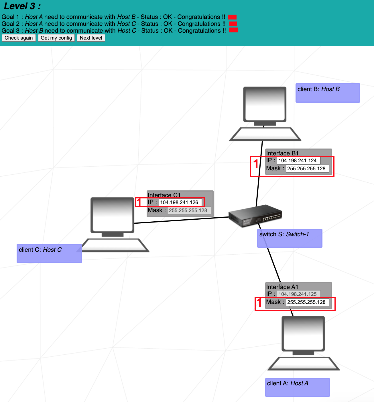
This exercise introduces the use of the **switch** (_Switch S_ in this example). The switch links multiple hosts of the same network together.
**1.** _Client A_, _Client B_, and _Client C_ are all on the same network. Therefore, they must all have the same subnet mask. Since _Client C_ already has the mask _255.255.255.128_, the mask for _Interface B1_ and for _Interface A1_ will also be _255.255.255.128_ (or in slash notation: _/25_).
The IP address of _Interface B1_ and _Interface C1_ must be on the same network range as the IP of _Client A_. This range is:
```
104.198.241.0 - 104.198.241.128
```
Excluding of course the network address and the broadcast address.
---
Level 4
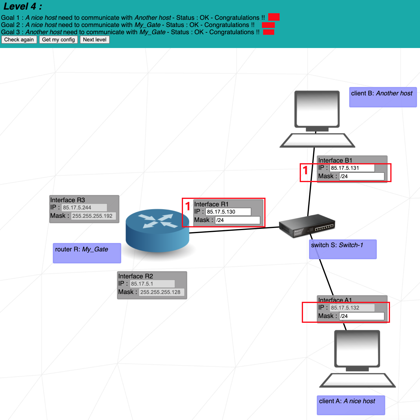
This exercise introduces the **router**. The router is used to link multiple networks together. It does so with the use of multiple interfaces (_Interface R1_, _Interface R2_, and _Interface R3_ in this example).
**1.** Since none of the masks on _Interface B1_, _Interface A1_, and _Interface R1_ are entered, we are free to choose our own subnet mask. A mask of **/24** is ideal as it leaves us with the entire 4th byte for the host address, and does not require binary calculations to find the range of possible host addresses.
The IP address of _Interface B1_ and _Interface R1_ must have the same network address as the IP address of _Interface A1_. With a subnet of _/24_, the possible range is:
```
85.17.5.0 - 85.17.5.255
```
Excluding the network address and the broadcast address.
Note that we did not interact with the router _Interface R2_ and _Interface R3_, since none of our communications had to reach these sides of the router.
---
Level 5
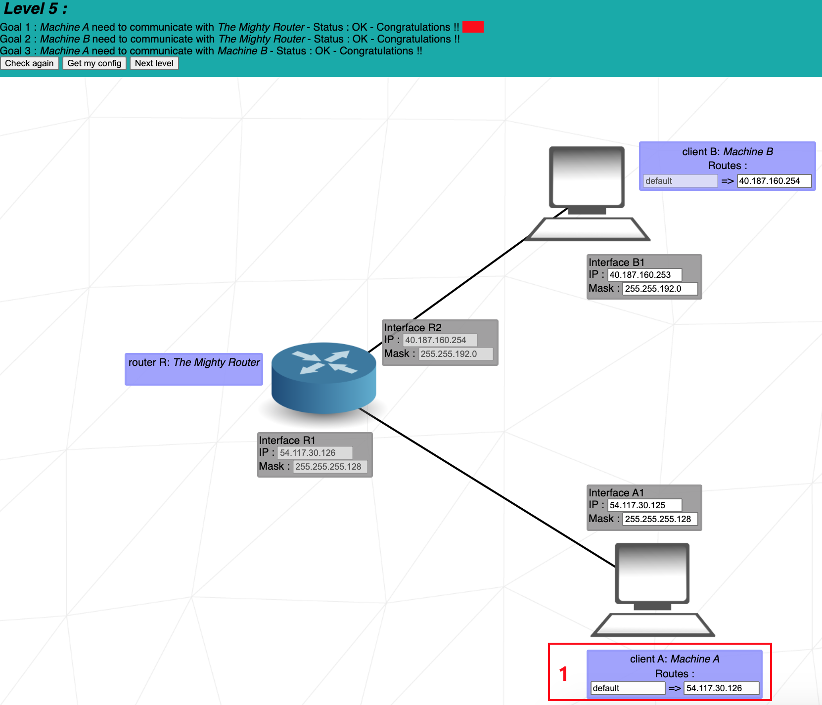
This level introduces **routes**. A route contains 2 fields, the first one is the **destination** of outbound packets, the second one is the **next hop** of the packets.
The **destination** _default_ is equivalent to _0.0.0.0/0_, which will send the packets indiscriminately to the first network address it encounters. A destination address of _122.3.5.3/24_ would send the packets to the network _122.3.5.0_.
The **next hop** is the IP address of the next router (or internet) interface to which the interface of the current machine must send its packets.
**1.** _Client A_ only has 1 route through which it can send its packets. There is no use specifying a numbered destination. The destination _default_ will send the packets to the only path available.
The next hop address must be the IP address of the next router's interface on the packets' way. The next interface is _Interface R1_, with the IP address of _54.117.30.126_. Note that the next interface is not _Interface A1_, since this is the sender's own interface.
---
Level 6
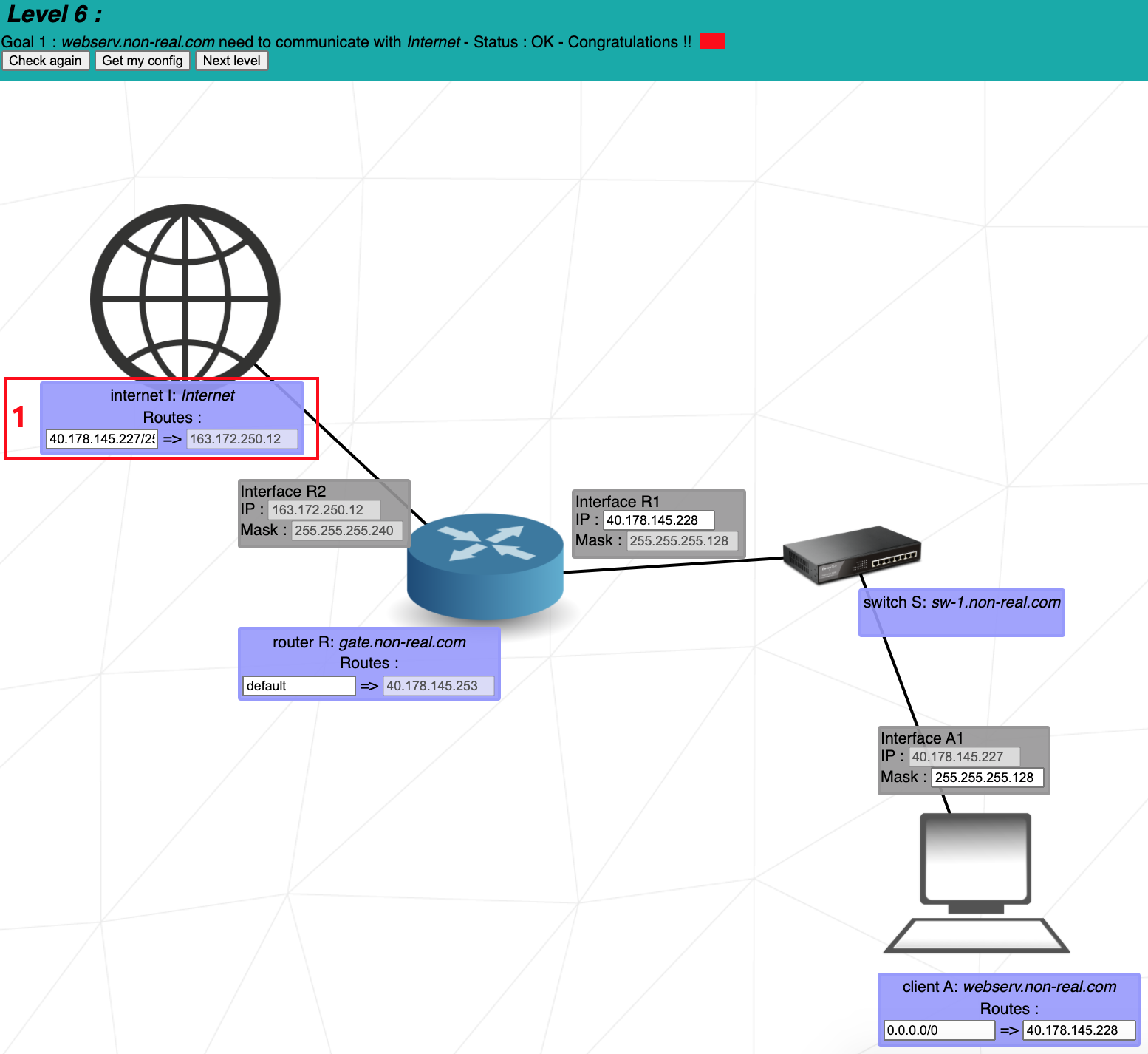
This level introduces the **internet**. The internet behaves like a router. However, if an interface is connected directly or indirectly to the internet, it **cannot** have an IP address in the following reserved private IP ranges:
```
192.168.0.0 - 192.168.255.255 (65,536 IP addresses)
172.16.0.0 - 172.31.255.255 (1,048,576 IP addresses)
10.0.0.0 - 10.255.255.255 (16,777,216 IP addresses)
```
**1.** The **next hop** of the internet is already entered, and matches the IP address of the _Interface R2_. Therefore we only need to bother with the destination of the internet.
The internet must send its packets to _Client A_. To do so, the internet's destination must match the network address of _Client A_. Let's find the network address of _Client A_:
_Client A_'s mask is _255.255.255.128_, which is equivalent to _/25_. This means that the first 25 bits of its IP address are its network address. We know then that the first 3 bytes (24 bits) of its IP address make part of its network address:
```
40.178.145.?
```
We now only need to find out if the 25th bit is a 1 or a 0.
If we convert the number 227 to binary, we get `11100011`. The first digit, which corresponds to the 25th bit, is a 1. Since only the 25th bit is part of the network address and not the remaining 7 bits, we get `10000000` for the last byte of the network address, which is 128 in decimal.
The full network address is:
```
40.178.145.128
```
With a range of _40.178.145.129 - 40.178.145.254_ for its host addresses.
We can now put this address of **40.178.145.128** in the Internet destination. The **/25** following the destination address represents the mask applied to its address.
A destination of _40.178.145.227/25_ is equivalent to the destination address _40.178.145.128/25_, since the mask of _/25_ will turn all the bits after the 25th to 0 to get the destination's network address.
---
Level 7
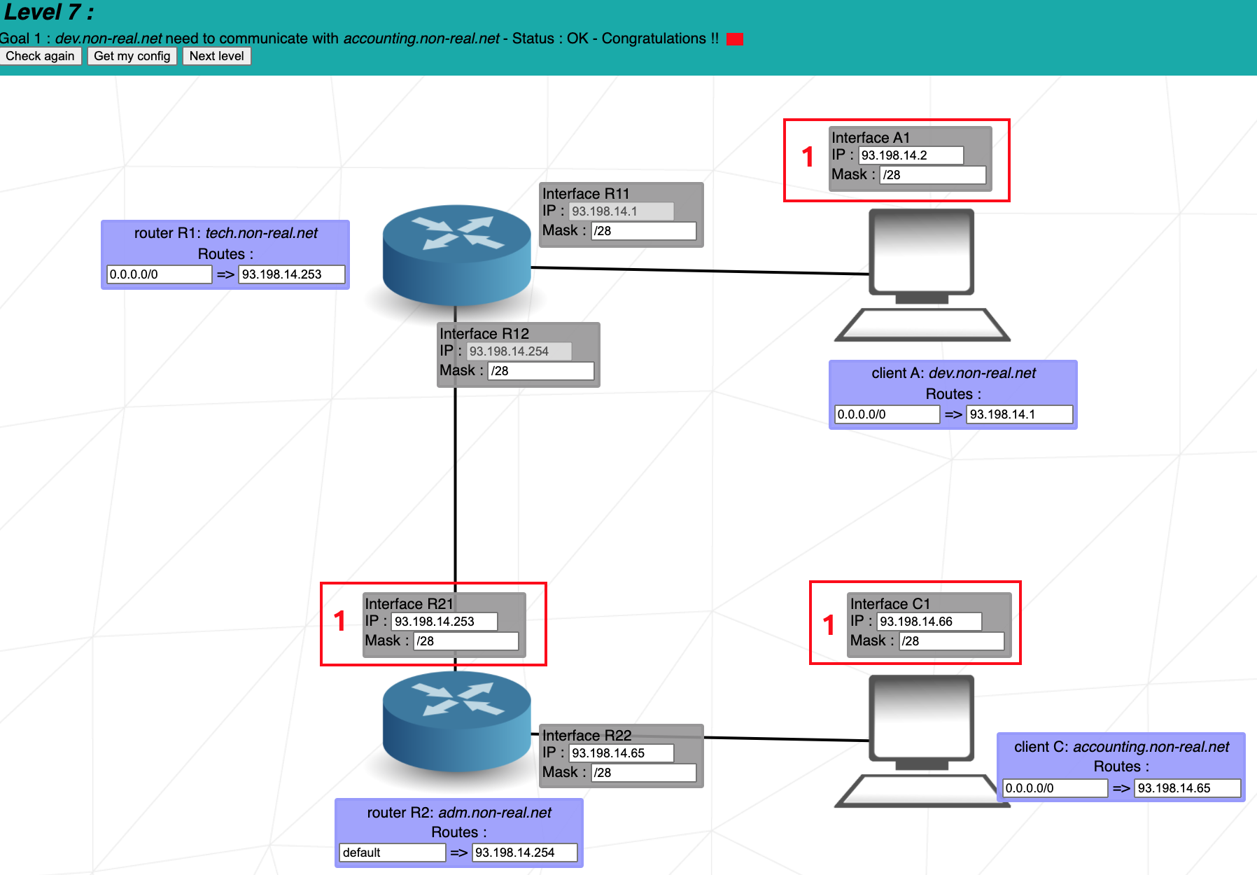
This level introduces the concept of **overlaps**. The range of IP addresses of a network must not overlap the range of IP addresses of a separate network. Networks are separated by routers.
**1.** We have 3 separate networks:
1. Between _Client A_ and _Router R1_.
2. Between _Router R1_ and _Router R2_.
3. Between _Router R2_ and _Client C_.
For _Interface A1_, we cannot choose our IP address freely since the IP of _Interface R11_ is already entered. Also, if we give it a mask of _/24_, the IP address range will overlap with the range of _Interface R12_, which is already entered. They would both be in the range of _93.198.14.0 - 93.198.14.255_.
Since we need addresses for 3 separate networks, it is convenient to split the last bytes of the address into 4 or more address ranges. We do this by using a mask of _/26_ or higher. The mask of _/28_ for example will give us 16 ranges, from which we use the following 3:
```
93.198.14.1 - 93.198.14.14 (Client A to Router R1)
93.198.14.65 - 93.198.14.78 (Router R1 to Router R2)
93.198.14.241 - 93.198.14.254 (Router R2 to Client C)
```
To calculate the possible ranges of a mask:
https://www.calculator.net/ip-subnet-calculator.html?cclass=any&csubnet=28&cip=93.198.14.2&ctype=ipv4&printit=0&x=97&y=13
---
Level 8

**1.** The hosts _Client C_ and _Client D_ will send packets to the internet, then the internet will respond by sending packets all the way back to the initial sender. To send these packets, the internet uses the destination _49.175.13.0/26_ to send the packets to the networks in the range of `49.175.13.0 - 49.175.13.63`.
All the receiving networks must be in this range, without overlapping each other.
**2.** On _Interface R23_ and _Interface R22_ we use the mask _255.255.255.240_ (or _/28_), to conveniently split the range of _/26_ from the destination address, into 4 separate ranges. This separation of 4 is necessary since we have the following 3 networks that must not overlap:
1. _Router R1_ to _Router R2_.
2. _Router R2_ to _Client C_.
3. _Router R2_ to _Client D_.
Each of these networks can then be attributed one of the following IP ranges with a mask of _/28_:
```
49.175.13.0 - 49.175.13.15
49.175.13.16 - 49.175.13.31
49.175.13.32 - 49.175.13.47
49.175.13.48 - 49.175.13.63
```
Note that the network address (first) and the broadcast address (last) must be excluded from each range.
**3.** The destination and next hop for the internet are already entered. We only need to enter the next hop for the _Router R2_, which is the IP on the _Interface R21_.
---
Level 9

This level is quite straightforward since the internet does not initially send its packets to a specific network. Therefore, the separate networks do not need to share a common address range. I would suggest simply following the 6 goals of the level one by one until the level is completed.
Remember not to use the network addresses from the reserved private IP ranges.
**1.** **Goal 3** states that we must connect _meson_ with the _internet_. The _internet_ will then have to respond to _meson_, so we enter _meson's_ network address in the _internet's_ destination.
**Goal 6** states that we must connect _cation_ with the _internet_, so we enter _cation's_ network address in the _internet's_ destination.
It is normal to have an empty field for the 3rd destination of the _internet_, and in _Router R1's_ destination. Not all fields of the routing tables need to be filled.
---
Level 10
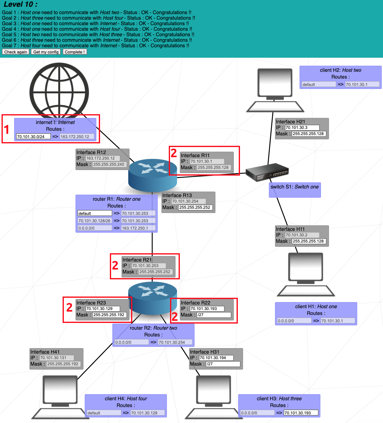
At this level, there are 4 different networks:
1. _Router R1_ to _Switch S1_
2. _Router R1_ to _Router R2_
3. _Router R2_ to _Client H4_
4. _Router R2_ to _Client H3_
**1.** The internet must be able to send its packets to all the hosts, so its destination must cover the range of networks of all the hosts.
_Interface R11_ and _Interface R13_ already have an IP address entered. This IP address only differs in its last byte. _Interface R11_ has for last byte **1**, and _Interface R13_ has for last byte **254**. To cover this wide range to IP addresses, we take a mask of **/24** for the _internet's_ destination. This destination will cover a range of `70.101.30.0 - 70.101.30.255`.
**2.** When choosing the IP addresses, we must make sure of 2 things:
1. The IP address is covered by the _internet_ destination.
2. The IP address range of the various networks does not overlap.
With the IP addresses already entered (greyed out), let's examine the ranges covered by the various networks:
1. _Router R1_ to _Switch S1_ - Covers the range **70.101.30.0 - 70.101.30.127** (mask /25).
2. _Router R2_ to _Client H4_ - Covers the range **70.101.30.128 - 70.101.30.191** (mask /26).
3. _Router R1_ to _Router R2_ - Covers the range **70.101.30.252 - 70.101.30.255** (mask /30).
4. _Router R2_ to _Client H3_ - ??? (mask ???).
The only IP addresses left for the network "Router R2 to Client H3" are **70.101.30.192 - 70.101.30.251**. We can pick any mask that will let us take 2 IP addresses from that range to put in _Interface R22_ and _Interface R31_.